| 6 |
Process flow for DeviceEditor |
Here is the basic process flow for using DeviceEditor to design a DNA sequence (for downstream automated assembly with j5):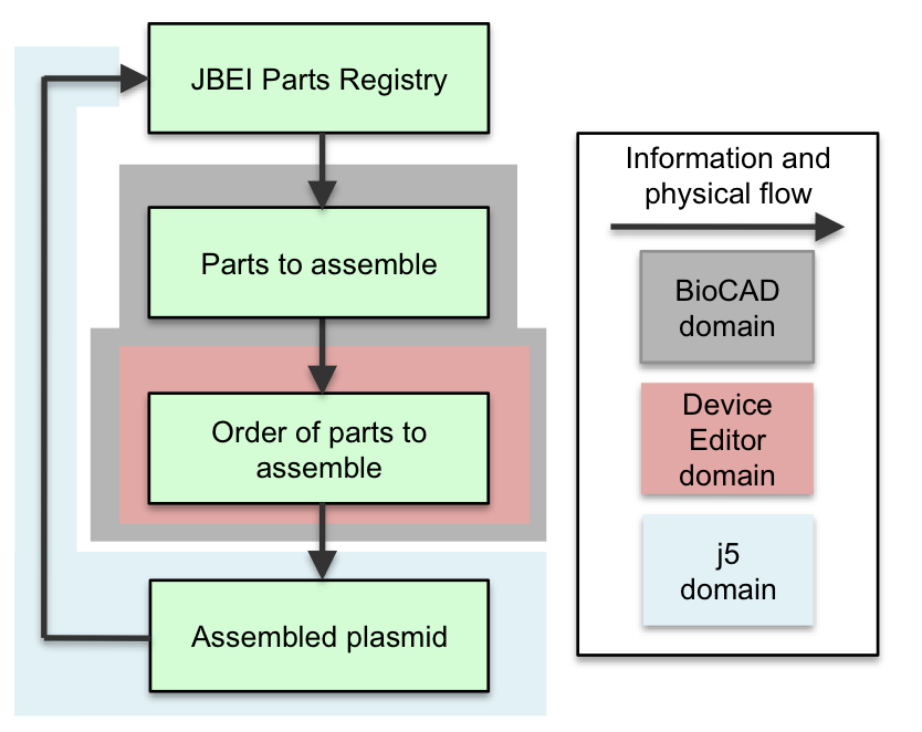 A researcher begins the DNA design process by identifying the component parts to be constructed together from a Registry of Biological Parts (e.g. the JBEI Parts Registry) or a local collection of DNA sequences. A variety of BioCAD tools (such as GLAMM (Bates 2011), ClothoCAD (Xia 2011), Tinkercell, SynBioSS, and SBW) may assist this process. Following the identification of the desired parts, in DeviceEditor, the user maps the DNA sequence (and feature annotations) underlying each part to a graphic icon. These icons, then, can be drag-and-dropped about a visual design canvas, with their spatial arrangement corresponding to their eventual (combinatorial) arrangement within the DNA (library) to be constructed. In addition, the user can assign j5 assembly protocol directives and Eugene design specification rules (Bilitchenko 2011A, Bilitchenko 2011B) to each part. After (optionally) setting the parameters that control the j5 DNA design process, the user submits the design to the j5 server. Following the j5-automated construction of the designed DNA, the user has the opportunity to inspect the anticipated DNA constructs, via links to opening the annotated DNA sequences in VectorEditor for visual assessment and validation. Following physical construction, the cloned plasmid(s) (or assembled linear fragment(s)) is (are) deposited into the parts repository. Specific (video) demonstrations of how to use DeviceEditor are provided in the next section, and highlight the various features and functionalities of DeviceEditor. |
|||||